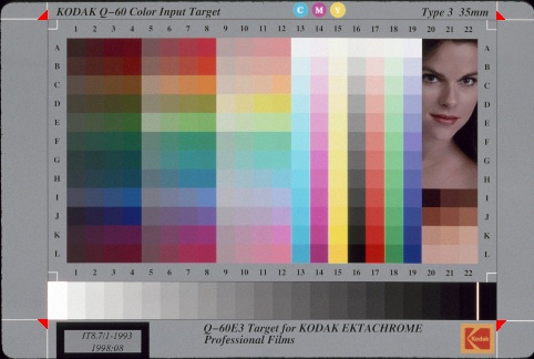
Scarse builds calibration profiles for your scanner by comparing actual raw scan of the test target with the colors it is supposed to have. To do that, it has to know where same-color patches are located on the scan. Typically, they are arranged on a rectangular grid. But the grid size and position in the scan is not fixed, as image area can be shifted and cropped. So, you must tell Scarse where the grid is on your particular scan. You do this by specifying grid geometry (like in X), not in pixels, but in percent of the total image dimensions (this is to make translation to different resolution scan easier). Here is an example:
Above is a scan of Kodak Q60E3 calibration target, with grid corners marked by bright red triangles (other Q60 targets are exactly like Q60E3). The grid takes up 84.2% of the width and 84.1% of the height of the scan, and is offset by 8.8% from the left and by 5.1% from the top. So the full geometry specification for the above scan is
-g 84.2x84.1+8.8+5.1You should find corners in your scan and work out numbers in a similar way. Or just crop the image to the corners, and say
-g 100x100+0+0
Eventually, when the GUI frontend is written, this boring step will be made automatic. But for now, you have to suffer...
[ Back to Scarse Howto | Scarse Project Homepage ]